



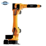


Mechanical Balancer Manipulator
The Mechanical Balancer Manipulator is a heavy-duty, rigid-arm articulated lifting and handling system designed for precise moving, positioning, orientation turning, and assembling of workpieces within defined industrial workstations. By integrating a counter-balancing system with a zero-gravity rigid mechanical link, the operator can directly guide offset loads, compensate for load torques, and achieve controlled alignment with minimal manual effort.
Technical Specifications
|
Specification |
Standard / Baseline Parameter |
|
Product Type |
Mechanical Balancer Manipulator |
|
Arm Type |
Rigid Articulated Jointed Arm |
|
Rated Load Capacity |
50 kg – 350 kg |
|
Working Radius |
1,500 mm – 3,200 mm |
|
Vertical Stroke |
1,000 mm – 2,000 mm |
|
Operating Pressure |
0.6 – 0.8 MPa (for pneumatic systems) |
|
Mounting Options |
Floor-Column / Overhead Stationary / Guide Rail |
|
Control Mode |
Manual direct operator guidance with pneumatic servo assist |
|
Load Movements |
Lift, Lower, Horizontal Transfer, Positioning |
|
Workpiece Rotation |
Manual or Pneumatic 90° / 180° / 360° Turning & Tilting |
|
End Effector Type |
Mechanical Clamp / Vacuum / Magnetic / Hook |
|
Operating Environment |
Indoor industrial applications (0°C to +40°C) |
Key Operational Advantages
Ergonomic Workstation Operation: Significantly cuts physical strain, preventing fatigue and workplace injury.
Rigid Position Control: Maintains precise load orientation throughout movement for zero-drift assembly.
Direct Operator Feedback: Tactile operator guidance ensures rapid, intuitive alignment during tight-tolerance assembly.
Flexible Layout Integration: Adapts easily to floor, ceiling, or moving crane systems to conserve valuable floor space.
Enhanced Part Protection: Controlled speed and custom soft-touch gripping surfaces prevent cosmetic or structural damage to workpieces.
Typical Applications
CNC Machine Loading & Unloading: Precise transfer of heavy blanks, shafts, and housings into lathe chucks or machining centers.
Automotive Manufacturing: Handling and positioning engine blocks, cylinder heads, gearboxes, brake discs, and EV battery modules.
General Machinery Assembly: Holding pumps, gearboxes, valves, and heavy fabrications during alignment and bolting.
Production Line Transfer: Transitioning heavy workpieces between adjacent conveyor lines or processing stations.
Maintenance & Tooling Changeover: Lifting and replacing dies, molds, and heavy machine components during maintenance.
System Architecture
|
Component |
Function & Features |
|
Rigid Arm |
High-rigidity articulated linkage that supports and guides the workpiece smoothly across the working envelope without tilting or swinging. |
|
Balancing System |
Dynamically neutralizes the load weight (pneumatic or mechanical balance) for near-zero effort handling. |
|
Mounting Structure |
Transfers static and dynamic forces safely to the floor, overhead steel structure, or traveling rail system. |
|
Operating Mechanism |
Ergonomic control handle equipped with proportional valves and main function switches. |
|
End Effector |
Custom-engineered gripping fixture designed around workpiece geometry, material, and surface sensitivity. |
|
Safety Protection |
Multi-tiered safety interlocks to prevent accidental load release or pressure drop hazards. |
Integrated Safety Features
Air-Supply Loss Protection: Built-in check valves and safety tanks prevent sudden dropping or drifting of the load if compressed air fails.
Misoperation Interlock: Prevents accidental release of the workpiece while the load is suspended in mid-air.
Low-Pressure Warning Indicator: Visual or audible alerts signal when line pressure falls below safe operational limits.
Controlled Lowering Speed: Speed-regulating valves prevent sudden, uncontrolled movements.
Mechanical Stop Limiters: Adjustable stops limit rotation and vertical stroke to prevent collision with surrounding equipment.
Installation & Mounting Options
Floor-Mounted Column: Fixed directly to a reinforced concrete slab; ideal for dedicated single-workstation applications.
Overhead Fixed Suspension: Mounted on ceiling structures or gantry frames to clear floor space for AGVs and forklift traffic.
Overhead Rail Mounted: Suspended from a single-track or double-girder bridge crane rail for broad multi-station coverage.
Pre-Installation Checklist: Verify concrete floor thickness/strength, overhead beam loading limits, dynamic load factors, obstacle clearances, and air line routing.
Customized End Effectors & Tooling
The end effector is custom-engineered to interface with specific component characteristics:
Mechanical Clamps & Grippers: For rigid metallic parts, castings, or shafts.
Vacuum Suction Fixtures: For smooth, non-porous sheet metals, panels, or glass.
Magnetic Lifters: For quick handling of flat or ferromagnetic plates.
Hook & Pin Attachments: For parts with existing lifting holes or eyelets.
Rotational & Tilting Heads: Integrated pneumatic or manual rotation modules (90° / 180°).
Quality Control Checks
Structural weld inspection and stress relief testing.
Precision alignment and smooth movement checks on all articulated arm joints.
Pressure leak and performance testing of pneumatic control circuits.
Dynamic balance response testing across maximum load spectrums.
Verification of interlock safety systems and emergency overload limits.
FAQ
Hot Tags: mechanical balancer manipulator, China mechanical balancer manipulator manufacturers, factory, assembled mounted manipulator arm, high accuracy manipulator arm, mobile manipulator arm, modular manipulator arm, parallel manipulator arm, workshop manipulator arm
You Might Also Like


Send Inquiry