



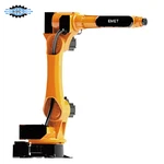


Machining Center Loading And Unloading Robot
The CNC Machining Center Loading and Unloading Robot automates raw material feeding and finished part removal, eliminating manual spindle downtime and ensuring continuous production. The robot precision-picks raw stock, loads it into the fixture/chuck, initiates the machining cycle, unloads the finished component, and transfers it to the designated output area.
Technical Specifications
|
Parameter |
Typical Specification |
|
Robot Type |
6-axis industrial robot |
|
Application |
CNC machining center loading and unloading |
|
Robot Payload |
Approx. 10–150 kg* |
|
Working Radius |
Approx. 1,500–2,700 mm* |
|
Repeatability |
Typically ±0.03–±0.08 mm* |
|
Number of Axes |
6 |
|
Installation |
Floor-mounted / side-mounted / customized |
|
Gripper |
Mechanical / pneumatic / vacuum / customized |
|
Material Supply |
Tray / pallet / rack / conveyor |
|
CNC Communication |
Digital I/O / industrial fieldbus / machine-specific interface |
|
Machine Door |
Automatic door interface where supported |
|
Fixture Interface |
Customized |
|
Control System |
Robot controller + electrical control cabinet |
|
Safety Protection |
Safety fence / interlocked door / light curtain / area scanner |
|
Operating Mode |
Automatic / manual / setup |
Key Advantages
Maximized Spindle Uptime: Achieve 24/7 continuous operation, including unassisted night-shift (lights-out) runs.
Elimination of Human Error: Consistent clamping alignment prevents fixture mis-seating and scrap parts.
Enhanced Workplace Safety: Keeps human operators away from machine enclosures, heavy workpieces, and cutting fluid mist.
Scalable Productivity: Easily adapt or reprogram the cell for new part families or add downstream processes as demand grows.
Rapid ROI: Typically achieves full payback within 12 to 18 months based on labor savings and production throughput gains.
Industrial Applications
Automotive: Crankcases, steering knuckles, brake discs, transmission housings, flanges, axle shafts.
Hydraulics & Fluid Power: Valve bodies, manifolds, pump casings, hydraulic cylinders, fittings.
General Machinery: Gear blanks, motor end-caps, bearing housings, structural brackets, precision fasteners.
Automated Operating Sequence
Raw Workpiece Pick: The robot retrieves a raw part from a designated material tray, pallet, or conveyor.
CNC Entry & Loading: Upon receiving the "Door Open / Ready" signal, the robot enters the machining area and positions the part accurately onto the fixture or chuck.
Clamping & Departure: The fixture clamps the part and sends a confirmation signal. The robot retracts from the machining area.
Machining Cycle Start: The machine door closes, and the CNC cycle begins. (For dual-machine cells, the robot transitions to service a secondary CNC during this phase).
Finished-Part Removal: Upon machining completion, the door opens, and the robot enters to pick the finished part.
Part Discharge & Secondary Operations: The finished part is transferred to the output station, inspection unit, or cleaning station.
Cycle Repeat: The robot returns to the raw-material station to begin the next cycle.
Customized Gripper Configurations
Mechanical / Pneumatic Gripper: Form-fit or friction-fit jaws tailored to specific workpiece profiles, offering secure locking force.
Vacuum Gripper: Ideal for flat, smooth-surfaced plate components.
Dual-Gripper System (Recommended): Holds a raw part and a finished part simultaneously. The robot unloads the finished part and immediately loads the raw part in a single door-open cycle, dramatically reducing machine downtime.
Custom Tooling Features: Coolant-resistant sealing, integrated air nozzles for chip cleaning, and adjustable jaws for family-part production.
Optional Automation Modules
Vision Guidance Systems: 2D or 3D vision systems locate randomly placed parts on conveyors or pallets, eliminating the need for expensive precision trays.
In-Line Quality Inspection: Integration with probe gauges, vision measurement, or laser scanners to automatically quarantine out-of-spec parts.
Part Flipping Units: Turn station to re-orient components for OP10 / OP20 multi-sided machining processes.
Drying & Cleaning Stations: High-pressure air-blow or wash tanks to clear coolant and metal chips before downstream handling.
Deburring Modules: Robot-driven or stationary spindle deburring to clean flash and sharp edges post-machining.
7th-Axis Linear Tracks: Heavy-duty linear track systems expanding the robot reach up to 30+ meters.
Information Required for Initial Feasibility Assessment
To evaluate your application and provide a preliminary proposal, please share:
CNC Machine Info: Model, controller brand, and auto-door/fixture status.
Workpiece Data: Part drawings (.STEP / .PDF), dimensions, and weight.
Process Details: Current machining cycle time and fixture photos.
Layout Constraints: Available floor space and preferred feeding method.
FAQ
Hot Tags: machining center loading and unloading robot, China machining center loading and unloading robot manufacturers, factory
You Might Also Like


Send Inquiry