



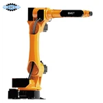


Multi-Machine Loading And Unloading Robot
A multi-machine tending system shares one industrial robot across several CNC machines within a single cell, eliminating the need for dedicated robots at every station.
While one CNC machine is in its machining cycle, the robot services adjacent machines that have completed theirs. Machine status, movement, and material handling priorities are fully synchronized through a central control architecture.
Technical Specifications
|
Parameter |
Reference Specification |
|
Robot Type |
Industrial articulated robot |
|
Axis Options |
4-axis / 6-axis |
|
Payload Options |
50 kg / 100 kg / up to 210 kg |
|
Working Radius |
Up to approximately 2732 mm for applicable configurations |
|
Repeatability |
Up to approximately ±0.08 mm / ±0.15 mm depending on robot model |
|
Protection Class |
Up to IP63 for applicable configurations |
|
Installation |
Floor-mounted or linear-rail-mounted |
|
CNC Configuration |
Multi-machine, application dependent |
|
Drive System |
Servo motor driven |
|
Controller |
Industrial robot controller + PLC |
Key Benefits
Lower Capital Investment: Serving multiple machines with one robot significantly reduces hardware and installation costs compared to dedicated single-machine robots.
Maximized Robot Working Time: The robot performs productive handling tasks at other stations while a machine is running, eliminating robot idle time.
Consistent Part Quality & Timing: Automated load/unload cycles eliminate human operator variability and ensure consistent positioning repeatability.
Centralized Production Control: Machine status, robot movements, safety interlocks, and priority queues are managed seamlessly under one unified control system.
Reduced Operator Fatigue: Shift personnel are freed from continuous manual material handling to focus on quality control, tool changing, and cell supervision.
Industry Applications
Automotive Components: Shafts, hub bearings, gear blanks, brake discs, engine brackets.
Precision Engineering & Industrial Parts: Valve bodies, hydraulic blocks, pump housings, flanges, bushings.
Aerospace & Energy: Precision fittings, turbine components, structural housings.
Medical Device Manufacturing: Implant blanks, precision instrument bodies.
System Architecture
Core Automation: Industrial robot, multi-axis controller, central PLC system, and machine-robot communication interface
End-of-Arm Tooling: Custom pneumatic, electric, or magnetic grippers (single or double)
Part Handling Stations: Raw-part loading stations, finished-part unloading stations, and positioning fixtures
Safety & Sensing: Safety fencing, door interlocks, part detection sensors, and gripper status monitoring
Optional Modules: Linear travel axis, part cleaning (air blow-off), dimensional inspection, vision guidance, and sorting equipment
Operational Workflow
Pickup: Robot picks a raw workpiece from a pallet, tray, rack, or conveyor.
Handshake: CNC sends a "Cycle Complete" signal; the robot verifies safety interlocks and enters the machine.
Exchange: Unloads the finished part from the chuck/fixture and loads the raw workpiece. (Note: Double grippers execute this swap in a single entry).
Verification & Start: Part seat detection confirms correct positioning; machining cycle starts, and the robot clears the area.
Next Station: Robot transfers the finished part to unloading/inspection stations, then moves to the next machine requesting service.
Typical Multi-CNC Layout Configurations
2-Machine Cell (CNC 1 ← ROBOT → CNC 2)
Best for: Machines with medium machining cycle times located within the fixed reach of the robot.
Typical Uses: Two CNC lathes, twin vertical machining centers (VMCs), or a turning-and-milling combination line.
3-Machine Cell (CNC 1 ← ROBOT → CNC 2 → CNC 3)
Best for: Longer CNC machining cycles that grant the robot sufficient travel and servicing headroom.
Layout: Circular/semi-circular arrangement around a fixed-mount robot.
4-Machine Cell (CNC 1 - CNC 2 - ROBOT + LINEAR RAIL - CNC 3 - CNC 4)
Best for: High-volume facilities or widely spaced machinery.
Feature: A 7th-axis linear travel rail expands the robot's operating range dynamically across linear layouts.
Gripper Systems & End-of-Arm Tooling
Grippers are customized based on part geometry, surface sensitivity, and process demands:
Pneumatic Grippers: Standard, robust solution for ferrous and non-ferrous metal parts.
Electric Grippers: Programmable stroke, position, and gripping force control for delicate or varied parts.
Magnetic Grippers: Ideal for flat ferrous components, plates, or blanks.
Double Grippers: Holds a raw part and a finished part simultaneously, cutting door-open exchange time by up to 50%.
Custom Jaw Designs: Tailored contact pads, V-blocks, and contoured fingers for irregular castings or polished surfaces.
Technical Project Evaluation
To receive a tailored layout proposal, cycle time simulation, and commercial quotation, please provide the following technical details:
CNC Machine Specifications: Brand, exact models, controller type, door opening dimensions, and current chucking/fixture setup.
Workpiece Parameters: Part drawings (2D/3D), dimensions, raw/finished weights, material, and surface constraints.
Production Cycle Metrics: Machining time per part, current manual load/unload time, and target daily output.
Factory Layout Plan: 2D floor layout showing machine spacing, available floor area, and operator access corridors.
FAQ
Hot Tags: multi-machine loading and unloading robot, China multi-machine loading and unloading robot manufacturers, factory
You Might Also Like


Send Inquiry